

Wellbore Diagram Submittals: Rules, Requirements, and Common Pitfalls
What Colorado operators need to know before the next filing
By: Aubrey Wood (Noonan)|Last updated: September 17, 2026
A wellbore diagram is rarely the reason a filing gets approved. It is frequently the reason a filing gets returned — and the operator who assumes the diagram on file is still accurate is the one who finds out during review.
A wellbore diagram may be one of the smallest attachments in an ECMC filing, but it can have a major impact on whether a submission moves through review smoothly. Under Rule 308.b.(2), certain Form 2 applications must include a wellbore diagram. Similar requirements apply throughout the regulatory lifecycle, including Rule 420 (Form 17), Rule 435 (Form 6), and Rule 803 (UIC applications). ECMC guidance also recommends wellbore diagrams for several other filings when they help demonstrate changes to the wellbore configuration.
A simple rule of thumb applies: if something changes downhole, ask whether the wellbore diagram needs to be updated. A complete, well-specific diagram helps an ECMC reviewer understand the well without having to piece information together from multiple attachments.
Why do wellbore diagrams matter?
ECMC's February 3, 2026 Wellbore Diagram Attachment Guidance consolidates diagram instructions that were previously spread across different forms and rule sections. That consolidation followed the Commission's broader rule renumbering and restructuring completed under the Complete Rules effective October 30, 2025 — the same rulemaking that moved wellbore diagram triggers into their current homes at Rule 308 (drilling and recompletion), Rule 420 (Bradenhead testing), Rule 435 (abandonment), and Rule 803 (UIC).
The updated guidance places greater emphasis on the diagram being a true-to-scale, well-specific visual representation rather than a generic schematic accompanied by a data table. That distinction is important. A reviewer should be able to look at the diagram and quickly understand what the well looks like today, what work has previously been performed, where casing, cement, plugs, perforations and other features are located, what is being proposed, and how the proposed work changes the existing wellbore.
For operators managing multi-well pads, re-entries, and injection conversions, this means the wellbore diagram is no longer treated as a supporting sketch. It is a discrete data product subject to the same completeness scrutiny as the narrative sundry itself. Incomplete or illegible diagrams are logged as a completeness defect, trigger deficiency letters and re-review cycles that can add weeks to a permit or sundry timeline, and can become a citable data point in an operator's compliance record.
What makes a strong wellbore diagram?
A strong wellbore diagram is built around three principles rather than a checklist. Together, these are more useful than treating the diagram as one more attachment to tick off a filing list.
Fidelity
What it means
The diagram accurately represents the specific well
What to look for
Actual casing, cement, plugs, perforations and historical work are shown
Where it fails
Boilerplate schematic with specifics in a side table
Legibility
What it means
The diagram is easy to read at any scale
What to look for
Appropriate scale, resolution and uncluttered presentation
Where it fails
Readable only when zoomed, or only in digital form
Completeness
What it means
Required information is represented
What to look for
Relevant depths, hardware, cement and trajectory information
Where it fails
Historic work erased by the most recent workover
An operator that internalizes these three principles produces diagrams that clear review on the first pass, regardless of which form they are attached to.
When is a wellbore diagram needed?
Not every ECMC form carries the same diagram requirement. Operators should confirm the requirements applicable to the specific filing rather than assuming a wellbore diagram is either always required or never required.
| Filing / Form | WBD Status | When to Consider It |
|---|---|---|
| Form 2 | Required for applicable activities | Deepening, re-entry, recompletion to a different reservoir, or sidetrack |
| Form 17 | Required in applicable circumstances | Bradenhead testing when a diagram has not previously been submitted or the configuration has changed |
| Form 6 NOI | Required | Notice of Intent to Abandon |
| Form 6 SRA | Required | Subsequent Report of Abandonment |
| UIC filings | Required in applicable filings | Injection well applications and conversions |
| Form 4 | Required | TA wells, Casing Repairs |
| Form 5 / 5A | Required | New Drill - Form 5/5As, Workovers - Changes to Casing (new perfs, etc) |
| Form 21 | Recommended | When a plug is left downhole and changes the configuration |
What is the difference between current and proposed?
One of the most important concepts in the current guidance is the distinction between the current (as-is) wellbore and the proposed configuration. For some filings, both views are required.
For Form 6 abandonment filings , the guidance identifies both a current diagram and a proposed plugging-procedure diagram as required. For Form 2 recompletions and deepenings, both current and proposed downhole configurations should be represented — either as two separate attachments or combined in one file, clearly labeled either way.
What should be on the diagram?
A wellbore diagram should contain enough information for the reviewer to understand the well's configuration without relying on a separate spreadsheet to reconstruct it. ECMC guidance breaks the required content into three groups.
1. Diagram header information
Every diagram should clearly identify the well.
| Required Information | Detail |
|---|---|
| Well name & number | As reported on the form |
| Diagram status | CURRENT (as-is) or PROPOSED; if both are attached, they may be two separate files or one combined file |
| Legal location | QtrQtr, Section, Township, Range, and Principal Meridian |
| API number | Well-specific API |
| County | Well location |
| Drawing date | Date the diagram was prepared |
2. Current permanent downhole features
The current diagram should tell the story of the well as it exists today.
| Category | Information to Show |
|---|---|
| Hole | Hole size, TD and PBTD |
| Cement | Quantity (sacks) placed for conductor, surface, intermediate, production casing and liners; top and bottom of cement with verification method (calculated or cement bond log); type; yield; and slurry weight |
| Casing | Size, weight, top and setting depth for each string |
| Casing equipment | Stage cementing tools (DV tools) |
| Perforations | Perforation depths |
| Formations | Formation tops |
| Downhole equipment | Bridge plugs, retainers, packers and fish |
| Existing cement | Quantities of cement in place on any of the above features |
| Sidetracks | Kick-off points (KOPs) |
The goal is not to show every piece of hardware. The goal is to show the features that matter to the well's configuration and the proposed regulatory action. A diagram becomes less useful when it is overloaded with detail — for example, showing every casing joint while making cement and critical depths difficult to read.
3. Proposed permanent downhole features
If the filing involves a change to the well, the proposed configuration should clearly show what will be different.
| Proposed Feature | What to Show |
|---|---|
| Deepening | Intended TD |
| Remedial cement | Top, bottom, quantity, yield and slurry weight |
| New plugs | Depth of reconfigured or intended bridge plugs and retainers |
| New equipment | Packers, fish or other intended features |
| Cement above equipment | Quantity and location of cement placed on top of these features, when applicable |
| Casing changes | Any change to the casing configuration |
| New perforations | Depths of any new perforations |
What are the most common wellbore diagram mistakes?
Most wellbore diagram problems are not complicated technical failures. They are problems with completeness, consistency or presentation — and every one of them is catchable before filing.
| # | Common Problem | Why It Matters |
|---|---|---|
| 1 | Required wellbore diagram is missing | Filing may be deemed incomplete |
| 2 | Only one diagram is included when current and proposed are both needed | Reviewer cannot compare configurations |
| 3 | Attachment is mislabeled | Creates uncertainty about what the diagram represents |
| 4 | Required diagram labels are missing | Well-specific information is unclear |
| 5 | Permanent downhole features are omitted | Diagram does not fully represent the well |
| 6 | Historic work is missing (annular cement, squeezed perforations) | Current diagram does not tell the full wellbore story |
| 7 | Diagram is difficult to read | Important information is obscured, whether by an over-detailed computer rendering or an illegible hand drawing |
| 8 | Sidetracks are not shown | Well history and configuration are incomplete |
| 9 | Data is placed in a side table instead of the schematic | Diagram fails as a true visual representation |
| 10 | Horizontal well is drawn as a vertical schematic | Well trajectory is misrepresented to the reviewer |
Do not erase the well's history
Two of those failures deserve more than a table row. The first is updating a diagram to show only the latest operation. Think of the wellbore as a timeline — original well, initial completion, workovers and squeezes, sidetracks, current configuration, proposed work — and the diagram as the full record of that timeline, not just its most recent entry. Deleting older work because it is no longer current makes the diagram misleading, and ECMC names this as a recurring problem.
Horizontal and directional wells need special attention
The second is trajectory. A horizontal or deviated well drawn as a conventional vertical schematic is a flagged defect regardless of how complete the depth data is otherwise — the reviewer needs the actual geometry of the well to evaluate isolation and proposed work. Make the deviation apparent through visual and/or textual notation.
Does the diagram pass the 30-second test?
Before submitting, hand the diagram to someone who did not prepare it and ask a single question: can you look at this for 30 seconds and tell me what the well looks like today and what is changing? If the answer is no, the diagram needs work — and it is far cheaper to hear that from a colleague than from a deficiency letter.
Do not wait until the filing
A wellbore diagram should not be a document that only gets updated when a Form 2 or Form 6 is being prepared. The annual Form 17 process is a natural checkpoint to confirm the diagram on file still accurately represents the well.
This matters more now than it did a year ago. ECMC is actively reviewing operator well files for missing wellbore diagrams, and the Commission's WebForms system includes a dedicated Wellbore Diagram Audit tool that makes that review efficient and searchable on the regulator's side. Operators should assume their inventory is being checked, and that a gap identified by ECMC first is a worse outcome than a gap identified internally.
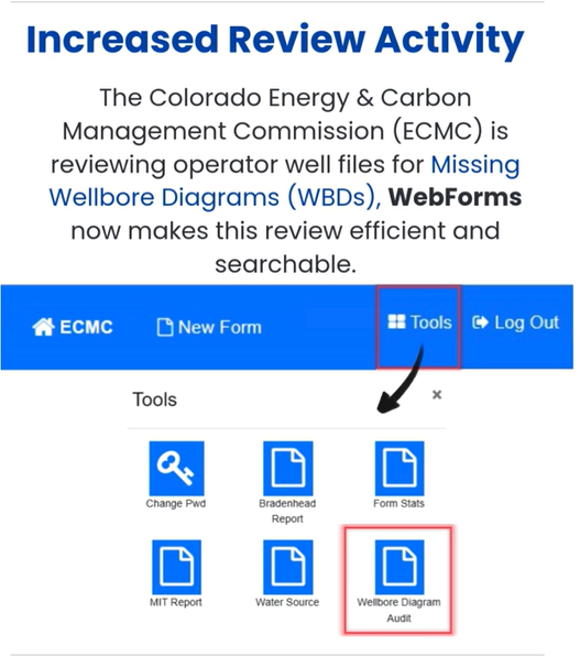
For operators with large inventories, a recurring wellbore diagram audit helps identify missing diagrams, outdated diagrams, inconsistent wellbore information, missing historical work, wells where the configuration has changed, and diagrams that need current or proposed updates.
The bottom line
A wellbore diagram is more than an attachment. It is a visual record of the well that helps ECMC understand the relationship between the well's history, current configuration, and proposed work — and when it does that job, the reviewer does not have to reconstruct the well from multiple documents. For operators, that means fewer questions, fewer avoidable completeness issues, and a smoother review.
Before filing your next ECMC sundry, ask one simple question: does this diagram clearly and accurately tell the story of this well? If it does not, the time to fix it is before the filing reaches the reviewer.
Questions worth answering before ECMC asks them for you
- Does this filing actually require a wellbore diagram, or is one only recommended, and have you confirmed which before assuming a diagram is not needed?
- What is changing downhole? Casing repairs, deepenings, recompletions and sidetracks all trigger a wellbore diagram submittal.
- Do you need a current diagram, a proposed diagram, or both, and is each configuration clearly labeled as one or the other?
- Is the diagram a true visual schematic, or a generic template with the well-specific data bolted onto a side table?
- Has the well's full history been preserved, including squeezed perforations, annular cement and previous sidetracks, or only its current state?
- If the well is deviated or horizontal, does the diagram make that obvious through visual or textual notation?
- Will the diagram read cleanly both on a printed page and on a reviewer's screen, not just at one resolution?
- When did you last audit your wellbore diagrams, and do you have a recurring process to keep them current rather than updating them only at filing time?
Which ECMC forms require a wellbore diagram?
Under Rule 308.b.(2), a wellbore diagram is required for Form 2 applications proposing to deepen, re-enter, recomplete to a different reservoir, or sidetrack an existing well. Diagrams are also required under Rule 420 for Form 17 Bradenhead testing when one has not previously been submitted or the configuration has changed, under Rule 435 for the Form 6 Notice of Intent to Abandon and Subsequent Report of Abandonment, and under Rule 803 for applicable UIC injection filings.
In practice the list is longer than the rule citations alone suggest. A wellbore diagram is also required with a Form 4 for temporarily abandoned wells and casing repairs, and with a Form 5 or 5A for new drills and for workovers that change the casing configuration, including new perforations. A diagram is recommended with a Form 21 when a plug is left downhole and the configuration has changed.
The practical test is simpler than working form by form: if something changes downhole, assume the wellbore diagram needs to be updated, and confirm the requirement for that specific filing rather than assuming a diagram is not needed.
Do I need both a current and a proposed wellbore diagram?
It depends on the filing. For Form 6 abandonment filings, both a current diagram and a proposed plugging-procedure diagram are identified as required. For Form 2 recompletions and deepenings, both the current and proposed downhole configurations should be represented.
When both are required, they may be submitted either as two separate attachments or combined into a single file. In either case, each configuration must be clearly labeled as current or proposed. Submitting only one diagram when both are needed is one of the most frequently cited completeness defects.
Can I use a generic wellbore diagram template with the well data in a side table?
No. ECMC guidance treats this as an incomplete diagram rather than a stylistic choice. If the well-specific information — casing sizes, cement tops and bottoms, perforation depths — lives primarily in a table alongside the schematic rather than being plotted at the correct depth on the diagram itself, the diagram does not function as a true visual representation of the wellbore.
The expectation is a true-to-scale, well-specific visual schematic in which the required data is incorporated into the drawing. A reviewer should be able to understand the well by looking at the diagram, not by cross-referencing a table against a generic outline.
How often should wellbore diagrams be reviewed?
A wellbore diagram should not be treated as a document that is only updated when a Form 2 or Form 6 is being prepared. The annual Form 17 process is a natural checkpoint to confirm the diagram on file still accurately represents the well.
ECMC is actively reviewing operator well files for missing wellbore diagrams, and its WebForms system includes a dedicated Wellbore Diagram Audit tool. For operators with large well inventories, a recurring internal audit helps identify missing or outdated diagrams, inconsistent wellbore information, missing historical work, and wells whose configuration has changed since the diagram on file was drawn.
Wellbore Diagram Audits
Not sure what ECMC has on file for your wells?
Most operators discover a wellbore diagram gap during review, when it already costs them time on a permit or a sundry. Progressive audits diagram inventories against ECMC records, identifies what is missing or outdated, and builds the recurring process that keeps them current.
Related Posts

Wyoming Sage-Grouse EO: 2026 Draft Changes
By: Ashley Noonan | Last updated: August 10, 2026 Greater sage-grouse in southwest Wyoming, Tom Koerner/USFWS, Public Domain, https://www.fws.gov/media/greater-sage-grouse-southwest-wyoming The short version: Wyoming’s draft 2026 Sage-Grouse Executive Order is not yet signed — the comment period closed July 31, and a final version is expected in rou
Colorado Form 6 Well Abandonment: What Makes a P&A Filing Stand Up to ECMC Review.
By: Julie Gordon (Webb)|Last updated: August 24, 2026 Form 6 filings rarely get attention until one comes back with comments — but they quietly decide whether a P&A program runs on schedule and whether your team spends its time on the next well or the last one. ECMC Form 6 is the well abandonment report […]

Utah’s New Oil and Gas Bonding Rules Are Live. Here’s What Operators Should Be Checking Now.
Progressive Insights · Regulatory Analysis By: Ashley Noonan | Last updated: August 10, 2026 The first overhaul of Utah’s financial assurance program in more than two decades took effect July 8 — and the Division’s bonding assessment letters are going out now. On July 8, 2026, Utah’s updated oil and gas bonding require
NMOCD 2023 Northwest Bradenhead Test Schedule Deadline 10.30.23
As a reminder, the deadline for “Area A” bradenhead tests is this coming Monday, October 30th, 2023. (All tests and forms submitted by November 1st) • Township 32 North, Ranges 6, 7, 8, 9, 10, 11, 12 West• Township 31 North, Ranges 6, 7, 8, 9, 10, 11, 12 West • Township 30 North, Ranges […]